Autocad Drawing Units Instead of Drawing Setup
Speaking of millimeters, here's another choice you have to make even before you choose your units of measure — and that's your system of measure.
Most of the world abandoned local systems of measure generations ago. Even widely adopted ones, like the Imperial system, have mostly fallen by the wayside (just like their driving force, the British Empire) — except, of course, in the United States, where feet, inches, pounds, gallons, and degrees-Fahrenheit still rule.
Make sure everyone agrees on the units being used. NASA once crashed a very expensive space probe onto Mars because of a mix-up between imperial versus metric systems.
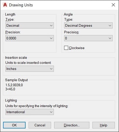
During drawing setup, you choose settings for length units (for measuring linear objects and distances) and angle units (for measuring angles between nonparallel objects or points on arcs or circles) in the Drawing Units dialog box. AutoCAD's length unit types are as follows:- Architectural units are based in feet and inches and use fractions to represent partial inches: for example, 12′3 1/2″. The base unit is the inch unless otherwise specified, so if you enter a number like 147.5, then AutoCAD will understand it to be 12′3 1/2″.
- Decimal units are unitless — that is, they're not based on any particular real-world unit. With decimal units, each unit in the drawing could represent an inch, a millimeter, a parsec, a furlong, a fathom, a cubit (if you're into building arks in case that rainy day should come), or any other unit of measure you deem suitable, from Danish alens to the Swiss zoll. An example would be 15.5.
- Engineering units are based in feet and inches and use decimals to represent partial inches: for example, 12′3.5″.
- Fractional units, like decimal units, are unitless and show values as fractions rather than decimal numbers: for example 15 1/2.
- Scientific units, also unitless and show values as exponents, are used for drawing really tiny or really large things. If you design molecules or galaxies, this is the unit type for you. Examples would be 15.5E+06 (which is 15,500,000) and 15.5E–06 (which is 0.0000155).

The Drawing Units dialog box.
AutoCAD's angle unit types are as follows:
- Decimal Degrees show angles as decimal numbers and are by far the easiest to work with, if your type of work allows it.
- Deg/Min/Sec is based on the old style of dividing a degree into minutes and minutes into seconds. Seconds aren't fine enough to display AutoCAD's precision capabilities, though, so seconds can be further divided into decimals. There is no degree symbol on a standard keyboard, so AutoCAD uses the lowercase letter d. An example would be 45d30′10.7249″. One nautical mile (6,076 feet) is approximately 1 minute of arc of longitude on the equator. David Letterman once said that the equator is so long that it would reach once around the world.
- Grads and Radians are mathematically beautiful but are not widely used in drafting. There are 400 grads, and 2*pi (6.2831…) radians, in a circle.
- Surveyor's Units type is similar to Deg/Min/Sec but uses quadrants (quarter circles) rather than a whole circle. An angle in Deg/Min/Sec might measure 300d0′.00″, while the same angle in Surveyor's Units would be represented as S 30d0′0.00″ E.
The unit types you'll most likely use are Decimal, Architectural, and Decimal Degrees. You'll know or be told if you need to use one of the other types.
AutoCAD always works internally to something like 16-digit accuracy. Changing the type of units changes only how values are displayed, suitably rounded off. For example, a line that's 15.472563 decimal units long would display as 12″3 1/2″ long when units are changed to Architectural. The actual length — and any calculations based on it — remains at 15.472563 and does not change to 15.5″.
When you use dash-dot linetypes and hatching in a drawing, it matters to AutoCAD whether the drawing uses an Imperial (inches, feet, miles, and so on) or metric (millimeters, meters, kilometers, and so on) system of measure. The MEASUREINIT and MEASUREMENT system variables control whether the linetype and hatch patterns that AutoCAD lists for you to choose from are scaled with inches or millimeters in mind as the plotting units.For both variables, a value of 0 (zero) means inches (that is, an Imperial-units drawing), whereas a value of 1 means millimeters (that is, a metric-units drawing). If you start from an appropriate template drawing, the system variable values will be set correctly, and you won't ever have to think about it.
So why are there two variables? Simple. MEASUREINIT (short for measurement initial) sets the default value for all new drawings, and MEASUREMENT changes the value for the current drawing.
AutoCAD automatically sets the measurement system according to your country when it's being installed, but it can be changed.
About This Article
This article can be found in the category:
- AutoCAD ,
Source: https://www.dummies.com/article/technology/software/design-software/autocad/choosing-units-autocad-221298/
0 Response to "Autocad Drawing Units Instead of Drawing Setup"
Post a Comment